
Info Current and Verified · Updated 06/2025
Short Description
Electrode manufacturing is the process of creating battery electrodes by mixing active materials into a slurry, coating this slurry onto a conductive foil, drying it, compressing it to achieve the desired density, and slitting it to size. Typically, conductive foils such as copper are used for the anode and aluminium for the cathode, though material choices may vary depending on different battery chemistries. This stage is critical for defining cell performance, as it establishes the electrochemical and mechanical properties of the electrodes. Precise control of technical parameters, processes, and equipment settings is essential to ensure high quality and consistency.
Relevant Material Streams
1.1Wet Mixing
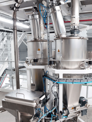
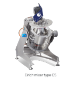
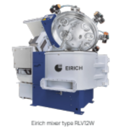
The mixing step involves carefully combining active materials, conductive additives, binders, and a solvent to produce a homogeneous, viscous slurry with precise rheological properties, ready for coating. Multiple process sequences are used, typically involving dry mixing followed by wet dispersing, though the exact order may vary depending on the electrode formulation, mixing technology and performance requirements.
The resulting slurry must meet strict consistency and stability criteria to ensure uniform coating. Transport to the next sub-process, Coating, is normally done via sealed containers or piped systems, often under controlled environmental conditions to prevent contamination or moisture uptake.
Monitoring slurry properties online and offline+
Controlling the slurry’s physical and chemical properties is essential for consistent coating performance. However, many key slurry attributes must be measured offline, which introduces delays. This slows down process feedback and correction, increasing the risk of defects. Properties often checked include: Homogeneity – Optical Testing, Cross-section Mass Analysis Agglomerates – Hegman Gauge, Microscopy Viscosity – Rheometer, Viscometer Gas Bubbles / Cavities – Acoustic Testing pH, Conductivity, Temperature – pH Meter, Impedance Measurement, Thermometer Composition – Gravimetric Weighing (Scales) Foreign Contamination – Magnetic Separation, Microscopy
Variability in raw material quality and how to develop consistent verification plan+
Mixing begins with raw materials—active powders, binders, additives, and solvents—but verifying their properties is often difficult, especially when working with bulk bags. Opening these materials for testing can expose them to air and moisture, compromising quality. Key properties like moisture content, particle size, and metal contamination must be verified, but comprehensive testing for every batch is often impractical. Common document and testing methods include: Certificate of Analysis (CoA) and Certificate of Conformance Humidity – Karl-Fischer Titration, Thermogravimetric Analysis (TGA) Porosity – Porosimeter Particle Size – Laser Diffraction / Scattering Metal Ions – Atomic Absorption Spectroscopy Purity – ICP-MS, Liquid Chromatography, Microscopy
Challenges in scaling from lab to industrial production+
Slurries behave differently when scaling from laboratory to production environments. Parameters like temperature, mixing time, rotor/stator speed, and vacuum level affect rheology—the flow behaviour of the slurry. If slurry is too thick (high shear), it may clog coaters; if too runny (low shear), it may flow unevenly in the coating process and lead to coating defects. Achieving the correct balance across various chemistries and recipes requires fine-tuning and process knowledge. Inconsistent slurry properties during scale-up can lead to poor coating adhesion, binder migration, and even electrode rejection, all of which reduce yield and drive up costs.
1.2Coating
In the coating step, the slurry is applied to a current collector foil (typically copper or aluminium) using tools such as a slot die, doctor blade, or anilox roller. Coating can be performed in a continuous or intermittent manner and may be applied to one or both sides of the foil—either sequentially or in a tandem coating setup.
This roll-to-roll process typically handles web widths up to 1200 mm. After coating, the foil passes through a drying channel where controlled heat evaporates the solvent. The coated web is then transported via rollers or non-contact levitation systems, and rewound onto an inner core for transfer to the next process step. Environmental controls are critical to prevent dust, moisture, or thermal instability from affecting coating quality.
High risk of coating defects+
Coating defects are common and in some cases, unavoidable, particularly in high-speed production. The goal is to minimize their occurrence and severity to stay within acceptable quality limits. Common defect sources include: Air bubbles or poor degassing from the mixing stage Agglomerated particles that block the slot die Contamination from the environment or upstream equipment Uneven drying leading to binder migration or cracking Even minor anomalies—like streaks, pinholes, or wet/dry transitions—can reduce yield and require inspection or rework.
Double-sided coating alignment+
In simultaneous double-sided coating, both sides of the foil are coated in a single pass. Ensuring proper geometric alignment between side A and side B is complex. Even minor misalignments can affect downstream calendaring and stacking. This tuning process is often iterative, involving trial-and-error adjustments—which becomes costly and time-intensive at large production scales, especially with high slurry consumption rates.
Maintaining precise mass-free zones, for tab welding for cylindrical cells+
For cylindrical cells, a mass-free zone—a narrow gap where no slurry is applied—is required on the foil for welding current collector tabs. Accurately defining this uncoated gap during the coating process is difficult. It demands precise control over slurry “bleed out”, die edge geometry, and web tension. Errors here can lead to scrap or poor welding performance in later stages, like winding and tab welding.
Achieving uniform coating thickness and edge quality+
Coating slurry evenly across the width of the foil is inherently challenging. Variations in slurry flow, foil tension, or slot die alignment can result in thickness inconsistencies, uneven mass loading, or poor edge definition. Defects like “ridges”, bleed-out, or tapering can compromise the electrode’s mechanical and electrochemical performance.
1.3Drying
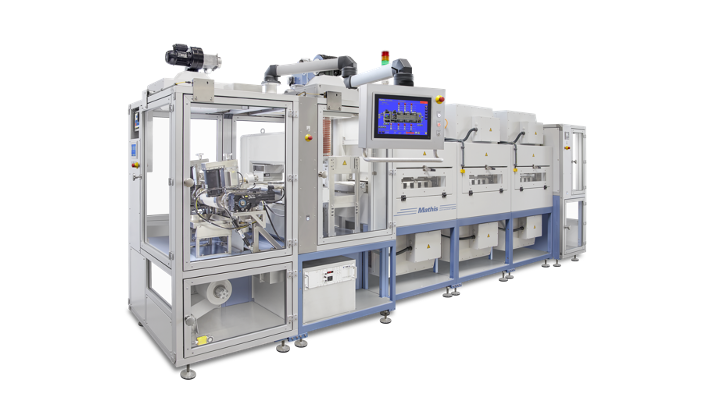
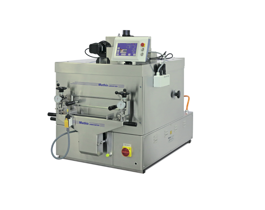
After the coating process, the coated aluminium or copper foils proceed directly to the dryer. The coated foil is transported through a drying channel using rollers or levitation systems. In cases of simultaneous coating, an airborne dryer is utilized to prevent damage to the coating. Heat removes the solvent, which is subsequently recycled or reused for afterburning purposes. The length of the dryer dictates the maximum speed of the process. The drying channel comprises different temperature zones to establish a specific temperature profile. Toxic solvents are recovered and either processed or recycled. After passing through the dryer, the foil is cooled to room temperature and rewound into a "mother" roll.
Efficient and Safe VOC Solvent Recovery (e.g. NMP)+
When solvents like N-Methyl-2-pyrrolidone (NMP) are used (common for cathodes), efficiently and safely capturing and recovering these Volatile Organic Compounds (VOCs) from the dryer exhaust is crucial. This is necessary for both environmental compliance (to prevent release of harmful VOCs) and economic reasons (as NMP is expensive and its recovery and reuse can significantly reduce material costs).
Preventing non-uniform drying and property variations+
Ensuring uniform drying across the entire width and thickness of the electrode coating is essential. Non-uniform drying can cause localized differences in porosity, density, binder distribution, and adhesion, leading to variations in electrochemical properties within the same electrode sheet and impacting cell-to-cell consistency.
Achieving complete solvent removal without defects+
It's critical to achieve complete solvent removal from the electrode coating. However, if the drying process is too aggressive or improperly controlled, it can lead to detrimental defects such as cracking, blistering, or binder migration (where the binder moves unevenly within the coating as the solvent evaporates), all of which compromise electrode integrity and cell performance.
Extended drying times and high energy demand+
A primary challenge is the long drying times required to evaporate solvents from the wet-coated electrodes, necessitating very long drying ovens in series production. These large ovens, operating continuously, result in very high energy demands, prompting investigation into new, faster, and more energy-efficient technologies like laser drying to shorten dryer length and reduce operational costs. The operation of large industrial drying ovens inherently involves high energy consumption due to the need to maintain elevated temperatures and significant airflow over extended periods. This contributes substantially to the overall energy footprint and operational cost of electrode manufacturing.
1.4Calendering
After drying, the coated electrode passes through the calendaring process, where it is compressed between precision rollers to achieve the desired thickness, density, and surface smoothness. This step is critical for tuning porosity, improving electrical conductivity, and ensuring mechanical adhesion between layers in the final cell.
Calendaring must balance compression with material integrity—too much pressure can cause cracking or delamination, while too little may result in low energy density and poor contact. The process is influenced by factors such as roller pressure, temperature, speed, and alignment. Uniformity across the width and along the length of the electrode is essential for consistent downstream performance.
Electrode deformation and creasing in pouch cells+
In pouch cells, electrodes typically include continuous coatings with mass-free zones for tab welding on each side. During calendering, the coated sections (hard, dense) and uncoated foil (soft, thin) deform unevenly under pressure. This mismatch can cause creasing, elongation, or edge distortion, which complicates tab alignment and welding during cell assembly. Managing line load and foil tension is essential to avoid defects in these transition zones.
Avoiding over-compression and material damage+
Excessive calendering pressure can crush active material particles, reduce porosity below acceptable limits, or cause binder redistribution—all of which degrade electrochemical performance. In severe cases, over-compression leads to mechanical defects such as cracking or delamination between layers, especially near the edges of the electrode. The current collector foil—typically aluminium or copper—can be stretched, wrinkled, or torn if calendering pressure is too high or unevenly applied. Such damage not only compromises mechanical integrity but can also lead to internal shorts or tab misalignment during later cell assembly steps.
Achieving uniform thickness and density+
One of the primary goals of calendering is to reach a specific electrode thickness and density uniformly across the full web width and length. Inconsistent compression can result in density gradients, which affect lithium-ion transport, thermal stability, and long-term cell performance. Variations can arise from misaligned rollers, foil inconsistencies, or non-uniform coating thickness from the previous step.
Calendering asymmetric anodes in cylindrical cells+
To increase energy density in cylindrical cells, anodes are often designed with an asymmetric structure—coated on one side, uncoated on the other. Calendering these single-sided anodes is challenging because the unsupported coating can flake or delaminate under pressure. This risk is especially high if the active material is brittle or poorly adhered. To avoid particle loss or damage, the roller pressure and alignment must be precisely controlled—often requiring iterative trial runs to tune parameters.
1.5Dry Mixing & Coating
Instead of mixing battery materials into a wet slurry, dry electrode manufacturing works directly with dry powders. This innovative approach skips the need for liquid solvents (like NMP or water) and the large, energy-intensive ovens used to dry wet-coated electrodes. The active material is first homogenized and pre-conditioned in a mixing process, arriving at the next stage as a powder or granules. This material is then fed to a pair of rolls that rotate in opposite directions, sometimes at different speeds. A dry film of the active material forms on the faster-moving roll.
Depending on the system, this dry film can either be generated first as a free-standing electrode and then applied to the current collector foil, or it can be calendered directly onto the substrate foil. Direct calendering and free-standing electrode production are currently the most promising dry processing technologies with high potential for quick adoption by industry. Before the dry film is applied, it is usually cut to the desired width.
The main goals of this method are to make battery production greener by using less energy and avoiding the harmful chemicals and solvent recycling steps common in traditional electrode manufacturing. This also simplifies factory setups and potentially allows for the use of new types of battery materials. Leading battery makers are already using or exploring these "dry" methods.
Dry coating equipment maturity, cost, and standardisation+
Specialised machinery for dry electrode manufacturing can be a significant investment, and because some techniques are newer, the equipment may be less standardized or have a shorter track record of reliability in high-volume settings compared to established wet coating lines. Finding experienced suppliers and ensuring long-term support for this emerging equipment can also be a consideration.
Managing dust and safety in dry coating+
Working with large volumes of fine dry powders (active materials, conductive carbon) creates a significant risk of airborne dust, and ATEX environments. This necessitates robust dust collection and air filtration systems to protect worker health, prevent contamination of sensitive manufacturing areas (like dry rooms), and avoid potential dust explosion hazards with certain materials. Static electricity can also exacerbate dust issues.
Scaling up to mass production+
Taking promising dry processing methods from laboratory experiments or small pilot lines to large-scale giga factory production is a major hurdle. It involves proving that the technology can scale to high volume manufacture achieving, high-quality electrodes consistently, reliably, and cost-effectively. This often requires significant investment in new types of automated machinery and process optimization, many promising business are working to demonstrate this scalability.
Achieving uniform dry mixing+
Mixing dry powders of active materials, binders, and conductive additives to achieve homogeneity, without a liquid solvent to help distribute them, is very challenging. Without a homogeneous dry mix, some parts of the electrode might have too much active material while others have too little, leading to inconsistent performance and a shorter lifespan for the battery cell.
Binder performance and availability+
Compared to well-established wet slurry methods (which often use PVDF binder in NMP solvent), there are currently fewer binder choices specifically designed and proven for dry processes. Dry binders, like PTFE used in fibrillation, require very specific processing conditions to create the necessary network to hold particles together and may not be compatible with all active materials. Developing new, effective, and low-cost dry binders is an ongoing research area.
Controlling electrode thickness and density+
Precisely controlling the thickness of the final electrode layer porosity of the particles and coating, is vital for battery performance. Dry processing techniques require highly specialised and accurate machinery to achieve the target specifications consistently. Variations in thickness or density can lead to uneven current distribution, localised overheating, and reduced energy storage capacity.
Ensuring good adhesion to current collector foil+
Making the dry electrode layer stick strongly and permanently to the metal current collector foil (copper or aluminum) is critical. Without the wet slurry's binder solution creating an initial bond during drying, dry methods rely on pressure, heat, or specialized adhesive primers. If adhesion is poor, the electrode layer can peel off (delaminate) during later manufacturing steps or when the battery is in use, causing the cell failure and potential safety issues.
1.6Slitting
After calendaring, the wide electrode rolls are precisely cut into narrower strips, known as daughter rolls or bobbins, to match the specific dimensions required for the target cell format—whether for cylindrical winding or pouch/prismatic stacking.
Slitting is performed using either mechanical rotary knives or laser cutting systems, depending on the material and required precision. Additional cleaning steps, such as fume extraction or rotating brush systems, may be integrated to remove fine particles generated during cutting.
Achieving clean, burr-free edges is essential to prevent short circuits, material shedding, or alignment issues during cell assembly. Sub-roll widths typically range from 100 mm to 300mm, but vary based on electrode design and cell specifications.
Controlling particulate generation and contamination+
Slitting is typically performed at high speeds—often exceeding 100 meters per minute—which makes achieving clean, burr-free edges a technical challenge. In mechanical slitting, key parameters such as blade geometry, tension settings, blade overlap, overspeed, and electrode alignment must be precisely controlled. Poor edge quality can lead to particle shedding, foiling defects, or short circuit risks during cell assembly.
Maintaining edge quality at high line speeds+
The slitting process inherently generates fine dust and particles, especially when working with dry, brittle coatings. Without proper extraction systems and environmental controls, these particulates can accumulate on electrode surfaces or within the machine, leading to contamination risks, tab welding issues, or internal short circuits in finished cells. Effective vacuum extraction, fume hoods, and cleaning mechanisms such as rotating brushes are essential to maintaining production cleanliness and product reliability.
Avoiding over-drying and coating damage+
While vacuum drying is generally a straightforward process, over-drying the electrode rolls can lead to cracking or embrittlement of the coated layers—particularly at the edges. This can create handling issues during cell assembly or introduce mechanical stress in the final cell structure.
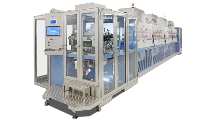

Electrode manufacturing is the foundation of battery cell quality. Six steps — wet mixing, coating, drying, calendering, slitting, vacuum drying — that drive cell performance, defect rates and yield.

A ready-to-use battery cell manufacturing procurement toolkit for electrode coating & drying lines: a full Invitation to Tender, a vendor requirements return matrix, and an equipment acceptance report — edit, issue to vendors, and evaluate.
The common defects that can arise during the various stages of electrode manufacturing (e.g., streaks or pinholes in coating, non-uniform density after calendering, burrs from slitting). It also seeks to understand the most effective methods for detecting these defects in-line or off-line and the best strategies for preventing their occurrence through optimized process control and material handling.
What are the critical control parameters in coating and drying?+
This focuses on identifying the critical parameters that must be precisely controlled during the electrode coating and subsequent drying processes to prevent common defects. Parameters like coating speed, slurry viscosity, die gap (for slot-die), drying temperature profiles, and air flow rates are crucial, as deviations can lead to issues like cracking, delamination, binder migration, or inconsistent active material loading.
What is the impact of slurry mixing quality on electrode and cell performance?+
This question explores how the quality of the slurry mixing process directly influences the final electrode uniformity and overall cell performance. Inconsistent or poor mixing can lead to uneven distribution of active materials, binders, and conductive additives, resulting in variations in electrode thickness, density, and electrochemical properties, which can negatively affect cell capacity, power, and cycle life.
Do you clarity and understand impact of product requirements on the process and equipment?+
This question emphasizes the critical importance of having clear and well-defined product requirements for the electrodes at the outset. Even small changes in electrode specifications (like target thickness, porosity, or active material loading) can have a significant impact on the necessary manufacturing processes, equipment settings, and ultimately, the feasibility and cost of production. A thorough understanding and upfront definition are key to process stability.
How does slurry mixing quality influence electrode uniformity and cell performance?+
The quality of slurry mixing plays a key role in determining electrode consistency and downstream cell behavior. Factors such as the degree of particle dispersion, homogeneity of binder and conductive additive distribution, and air incorporation during mixing all influence the uniformity of the final coating. Variations introduced during mixing can affect coating quality, drying behavior, and calendering outcomes—ultimately shaping the electrode's porosity, conductivity, and adhesion. These differences translate to non-uniform current distribution, which may lead to localized overpotential, temperature gradients, or accelerated degradation. Over time, this can impact capacity retention, cell balance, and overall safety in module or pack configurations.
What to think about when choosing a cutting method for electrode slitting+
Select the appropriate cutting method (rotary, shear, score) based on electrode material and thickness. Regularly inspect and replace knives to maintain cut quality. Implement procedures to prevent contamination of the slit electrodes by particles generated during cutting and ensure effective extraction is included
What to look for in safe and efficient dry powder processing equipment+
When considering equipment for dry powder processing in electrode manufacturing, safety is paramount. Ensure any machinery includes robust dust control and extraction systems to manage airborne particles, along with features to mitigate static electricity, explosion prevention measures (ATEX). Beyond safety, rigorously evaluate the equipment's proven results, look for evidence like case studies or demonstrations, showing the machines successfully producing electrodes that meet required quality specifications. Also, thoroughly investigate the system's measurement capabilities and anticipated maintenance needs, as these will significantly impact long-term operational costs and efficiency.
What to look for in a high-performance electrode drying oven system+
Ensure the drying ovens provide uniform temperature distribution and efficient solvent removal without overheating or damaging the electrode coating (e.g., binder degradation, cracking). The system should allow precise control over temperature profiles and air flow rates. Effective solvent recovery is critical for NMP.
What to look for in high-performance coating systems+
Prioritise coating systems that deliver exceptional uniformity in coating thickness (both down-web and cross-web). The system must maintain stable operation at the desired production speeds and offer precise control over coating parameters (e.g. pump rate, web speed, die gap). It is also important to understand flexibility in the coating systems and key in-line measurement systems.
What to look for in mixing+
- Mixing performance: The mixer must ensure excellent dispersion of solids and create a stable, homogeneous slurry across all material types. Check for uniformity, lack of agglomerates, and effective wetting of particles.
- Rheological consistency: The system should maintain slurry viscosity and solid content within tight tolerances, especially for formulations sensitive to shear rates or temperature.
- Inline monitoring capabilities: Consider whether the system supports real-time analysis tools for parameters like viscosity, conductivity, temperature, and pH—critical for process control and quality assurance.
- Material and solvent handling: Verify the mixer’s capabilities for powder dosing accuracy and solvent compatibility. Ask about limitations in handling low-flashpoint or corrosive solvents.
- Footprint, environment and integration: Assess whether the mixer’s physical size and power requirements fit your facility, and whether it interfaces seamlessly with downstream equipment such as coating and drying lines, and Manufacturing Execution Systems (MES)
- Maintenance and usability: Look for accessible design features for blade changes, cleaning, and inspection. Downtime due to maintenance can be costly in high-volume operations.
What to think about in mixing+
- Mixing method and design: Choose between batch and continuous mixing based on your production strategy. Consider whether your process benefits from high shear mixing, vacuum mixing, or multi-stage sequences for complex chemistries.
- Formulation compatibility: Ensure the system can handle the full range of active materials, binders, and solvents used in your recipes—including those with high viscosity, abrasive properties, or sensitivity to moisture.
- Control systems and flexibility: Look for equipment that offers programmable mixing recipes and precise control over speed, time, temperature, vacuum, and accurate material dosing. This allows you to fine-tune the process for different materials, solutions and manufacturing scales.
- Data integration and traceability: Opt for mixers that connect with a Manufacturing Execution System (MES) or digital control platform to capture process data for quality tracking and continuous improvement.
- Cleaning and cross-contamination prevention: Evaluate how easily the system can be cleaned. Campaign-based production (for different chemistries) requires robust cleanout procedures and quick-change features to minimize contamination risks and downtime.
This is one stage of the full battery cell manufacturing workflow
See how Electrode Manufacturing fits into the end-to-end Battery Cell Manufacturing journey.
Back to the full guide →