Battery Pack Assembly Toolkit: Guide, Equipment Shortlist & Design Calculator
Battery pack assembly for cylindrical lithium-ion cells, stage by stage: cell acceptance, sorting, loading, surface treatment, cooling integration, cell connection, module verification, high-voltage pack integration, pack testing and commissioning. White paper, equipment and partner shortlist, and pack design calculator included. By Mahmoud Hermes.

 Switzerland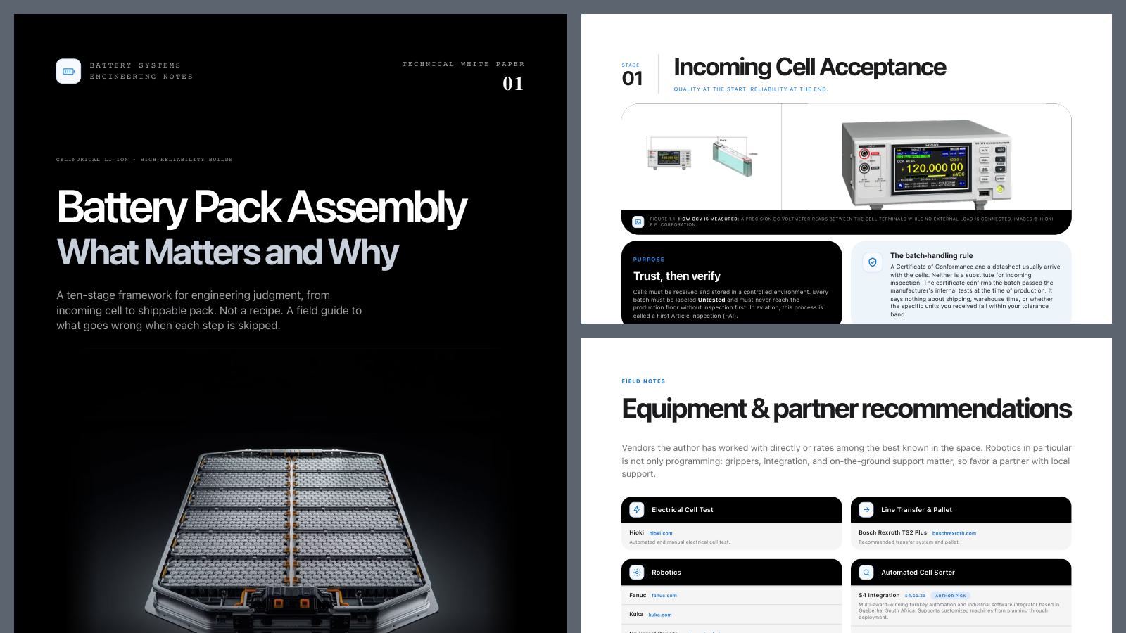
- Sign in to download
Battery Pack Assembly: Technical White Paper (PDF)
19 pages · PDF · includes the equipment & partner shortlist and image sources
- Sign in to open
Battery Pack Design Calculator (BPD Calc)
10 calculators · runs in your browser · nothing you enter is stored
Free account required. Already have one? Sign in.
Most articles about battery pack assembly describe what happens. This one describes what matters, why it matters, and what goes wrong when it is skipped.
Every stage below reflects real production experience with cylindrical lithium-ion cells in high-reliability applications. The intent is not a recipe but a framework for engineering judgment.
Multiple cell formats exist, including cylindrical, pouch, and prismatic. This article covers cylindrical cells, which dominate high-power applications due to their mechanical robustness and high automation potential. The sequence below applies from the moment you receive the cells through delivery of a complete battery pack ready for shipment.
One promise runs through every stage: traceability. From each individual cell to every fastener, every component is tracked on the MES. For any recall or defect, you must be able to trace a part back to its batch, its shift, and the exact day it was built.
Stage 1: Incoming Cell Acceptance
Quality at the start decides reliability at the end. Cells arrive from the supplier with a Certificate of Conformance and a datasheet, and the temptation is to send them straight to the line. Stage 1 exists to stop that. The cells are first received into a controlled environment and labeled Untested, because nothing that has not been inspected may reach the production floor. A representative sample is then measured electrically and inspected physically, because the certificate only proves what the batch looked like when it left the factory, not what shipping and storage did to it since. Finally the OCV readings are plotted as a distribution, because one reading describes a single cell while the spread describes the batch, and it is the spread that sets the sorting bands for Stage 2.
- Trust, then verify. Cells must be received and stored in a controlled environment. Every batch must be labeled Untested and must never reach the production floor without inspection first. In aviation, this process is called a First Article Inspection (FAI).
- The batch-handling rule. A Certificate of Conformance and a datasheet usually arrive with the cells. Neither is a substitute for incoming inspection. The certificate confirms the batch passed the manufacturer's internal tests at the time of production. It says nothing about shipping, warehouse time, or whether the specific units you received fall within your tolerance band.
- The minimum test set. Start by testing a representative sample from each received batch. The author's recommended starting point is 5 to 10% of the batch, selected across cartons and pallet positions. This is a practical screening rule, not a universal automotive requirement. Increase the sample or move to 100% screening when supplier performance, application risk, or the measured distribution warrants it.
Electrical tests
- Open Circuit Voltage (OCV) confirms voltage within the specification window.
- Internal Resistance (DC-IR or AC-IR); low and consistent IR means high power capability.
- Delta-OCV as a self-discharge indicator; a high value signals internal issues.
- Capacity verification (optional, depending on application criticality).
Physical inspection
- Can geometry: any visible deformation of the can wall, dent, or asymmetry at the bead is a reject.
- Positive cap: deformation or center-pin displacement affects wire-bond adhesion and current capacity.
- Negative terminal: assess scratches, oxidation, or residue against your surface-prep plan.
- Can wrapper: inspect for tears, punctures, or delamination.
- Acceptance is not grading. Stage 01 establishes whether the received batch is suitable to enter production. Individual cell grading and assignment to matched bins occur in Stage 02: Cell Sorting.
- Understanding the OCV distribution. A single OCV reading tells you about one cell. The distribution tells you about the received batch. Measure the incoming sample only after the cells have stabilized at the same temperature, state of charge, and rest condition. Plot the results before setting provisional sorting limits. The objective is to see the center, spread, unusual sub-groups, and potential outliers before Stage 02 grades individual cells.

ΔOCV screening, interpretation, and recommended action:
- ≤ 10 mV: tight incoming distribution. Accept the sample result and release the batch to Stage 02 sorting, subject to all other checks.
- 10 to 15 mV: moderate spread. Confirm temperature and rest time, then increase the sample and apply closer sorting.
- 15 to 20 mV: wide spread. Hold the batch, remeasure after stabilization, and investigate mixed SOC, age, or transport conditions.
- > 20 mV: excessive spread. Segregate pending engineering and supplier disposition; do not release directly to pack assembly.
Author-proposed screening bands, not an ISO, IEC, or SAE automotive limit. ΔOCV is the maximum minus minimum OCV within the stabilized incoming sample. Confirm limits against the cell datasheet, chemistry, temperature, SOC, rest time, and validated process capability.
Stage 2: Cell Sorting
Every cell earns its place in the pack. Stage 1 cleared the batch. Stage 2 looks at each cell on its own. Every cell is first scanned by its serial number or QR code, because from here on its test data must follow it through the line. It is then measured electrically, inspected physically and assigned to a grade bin, because an accepted batch can still contain individual defective cells, and one of them is enough to cause a failure in service. Only cells that pass move on to loading, and only with their record attached, because without that link no root-cause analysis is possible later.
Once FAI is approved and the batch is accepted, the label changes from Untested to Verified and Ready for Production. Accepting the FAI does not mean every individual cell is in good condition.
Depending on your industry and risk tolerance, 100% electrical and physical inspection of all cells is strongly recommended to prevent any defective unit from entering production.
- Low volume. Benchtop fixtures and manual measurement work, though the approach is labor-intensive.
- Higher volume. Automated bespoke machines with vision systems read each cell's QR code, inspect can geometry, and run the full electrical suite, sorting output into accepted and rejected bins. Precision and throughput are not comparable to manual methods.
Traceability starts here. Every cell that enters production must have its serial number or QR code scanned and linked to its measured OCV, IR, and grade bin before it advances. If you cannot trace a cell from its position in the finished pack back to its incoming test data, you cannot perform a meaningful root-cause analysis when something goes wrong.

Stage 3: Cell Loading
Orientation is not a detail. It is the design. The sorted cells are first placed into the carrier, the honeycomb or cell holder, because the carrier fixes the spacing, supports the cells mechanically and in some designs forms the path for side cooling. The orientation of every cell is then checked against the design, because a single reversed cell breaks the electrical layout and the cooling surface that the following stages depend on. Only after that check does the assembly advance, by two-person verification at low volume or by a vision system at higher volume.
After sorting, cells are loaded into the carrier, commonly called the honeycomb or cell holder. The carrier design varies between manufacturers and serves multiple functions: mechanical support, cell spacing, and in some designs a pathway for side cooling.
- Cell orientation must be controlled and verified at this stage. Some designs, such as the Lucid architecture, orient all cells in the same direction to present a flat bottom surface optimized for direct base cooling. Others, common in home-storage products, alternate positive and negative terminals across both faces. Whichever your design requires, a dedicated quality check must confirm correct orientation before the assembly advances.
- Low throughput. Manual loading with a two-person verification rule is acceptable, where each operator checks the other's work.
- Higher throughput. An automated vision system with a go/no-go output, compared against a stored reference pattern, is the appropriate upgrade.

Stage 4: Surface Treatment
The joint is only as good as the surface beneath it. Before any bonding, welding or adhesive is applied, the cell terminals and can surfaces are cleaned, because as delivered they carry oxide and contamination that weaken every joint made on them. The method is chosen to match the production stage, because chemical cleaning is only fit for a prototype, plasma is the production standard for flat terminals, and laser is the precision option for complex geometry. In production the equipment is enclosed with extraction, because plasma fumes and laser radiation are operator hazards, not just process variables.
Battery cell terminals and can surfaces as delivered are not ready for bonding, welding, or adhesive application. The surface condition determines the quality and long-term reliability of every electrical and mechanical joint in the module.
Three methods are available: chemical cleaning, plasma treatment, and laser cleaning. Each has a different capability level and production fit.
Chemical cleaning (IPA or acetone, manual; prototype only). Acceptable only for one-off prototypes where a single engineer controls the entire process. Not suitable for production: poor repeatability, invisible solvent-residue risk, and health and fire hazards.
Plasma treatment (atmospheric, inline or handheld; production standard). The production-standard method for most cylindrical cell terminal applications. UV photon bombardment removes organic contamination while ionic bombardment reduces the surface oxide layer, producing a clean, high-energy surface that wets uniformly and bonds reliably. Suitable for flat terminal contacts and compatible with wire bonding and adhesive processes.
Laser cleaning (pulsed fiber, ablation; precision option). Higher capital cost than plasma but superior spatial precision, cleaning exactly the bonding zone without affecting the wrapper or surrounding geometry. Best for prismatic cell terminals or cylindrical positive caps with complex geometry. Can be integrated with a laser welding station, reducing equipment footprint and capex to a single machine.
- Process requirements (plasma and laser). Both require enclosed equipment with appropriate extraction. Plasma generates fumes that present a long-term respiratory hazard if not properly controlled; the machine must operate in a closed enclosure with active extraction. Laser systems require a laser-class-appropriate enclosure and operator eyewear matched to the specific wavelength and power class.

Stage 5: Cooling System Integration
Plan the line around the thermal architecture, not after it. Cooling is not one station but several operations spread along the line, and their position is set by the thermal design. Side cooling panels go in during or right after cell loading, because they must sit against the cells before the electrical connections are made. Bottom cooling plates are attached once the module is assembled, and foam or phase-change material between the cell rows is applied after cell connection. Each step is verified with a measurable check and recorded against the serial number, because a cooling interface applied out of sequence does not fail on the line, it fails months later in the field.
Cooling in a battery module is not a single assembly step. It is a sequence of operations distributed across the production line, and where each operation falls depends entirely on your thermal architecture.
- Side cooling panels are installed during or immediately after cell loading, before electrical connections are made.
- Bottom cooling plates are attached after module assembly is complete.
- Foam or phase-change materials injected between cell rows are applied after cell connection.
If your design uses more than one cooling method, this stage repeats at multiple points on the line. Plan your assembly sequence around your thermal architecture from the start, not as an afterthought.
- The failure is delayed, not immediate. The consequence of getting this step wrong is not an immediate failure. It is a thermal failure six months into operation, when cells that should be running at 45°C are running at 62°C because a cooling interface was applied incorrectly, incompletely, or out of sequence.
- How to avoid it. Use measurable process checks such as cooling-plate leak integrity, thermal-interface coverage, fastening verification, and coolant flow or pressure-drop testing. Record the results against the module or pack serial number in the MES.

Stage 6: Cell Connection
The joint that defines your process, safety and capex. With cells loaded and cooling interfaces in place, the cells are now joined into one electrical unit. Busbars are set to carry current between cell groups and between modules, and each cell terminal is then connected to the busbar by one of three methods. That method is chosen early, because it decides how much heat goes into the cell, whether each cell has its own fuse, and what the line costs: resistance spot welding for consumer and home storage, laser welding for automotive volume, and wire bonding where per-cell fault isolation matters, as in aerospace and high-voltage automotive.
Once cells are loaded and cooling interfaces are in place, the cells must be electrically interconnected through busbars and cell-level interconnects working together. The busbar carries current between groups of cells and between modules. The cell-level interconnect is the joint between each individual cell terminal and the busbar, and the choice of method here defines your process, your safety architecture, and your production line investment.
Resistance spot welding (lowest capex; consumer and home storage). A high-current pulse fuses a nickel or nickel-plated steel strip directly to the cell terminal using two electrodes pressed against the contact surface.
- Advantage: lowest capital cost and simplest line integration; the dominant method in consumer electronics and home storage by total unit volume.
- Disadvantage: high heat input directly into the cell terminal, and no inherent fusing function, so it requires a separate overcurrent protection layer.
Laser welding (automotive EV standard). A focused laser beam melts and fuses a metal interconnect tab or busbar directly to the cell terminal with precise energy control.
- Advantage: low heat input, high joint repeatability, and compatibility with aluminum and copper interconnects; the standard in high-volume automotive EV production.
- Disadvantage: high capital cost and the need for validated welding recipes per terminal type, with sensitivity to surface contamination causing weld defects.
Wire bonding (aerospace and high-voltage automotive). Ultrasonic bonding attaches individual aluminum ribbon wires from each cell terminal to a busbar or PCB pad. Each wire is a discrete, independent connection.
- Advantage: each wire acts as an inherent fuse, giving per-cell overcurrent protection and automatic fault isolation with no additional components, which is why it is increasingly specified in aerospace and high-voltage automotive.
- Disadvantage: lower throughput per connection than a welded strip, and mandatory surface pre-treatment (plasma or laser cleaning) before bonding, adding a process dependency that must be tightly controlled.

Stage 7: Module-Level Electrical Verification
Catch it on the bench, not in a sealed pack. The connected module is now an electrical unit for the first time, so it is verified before anything else is added. Every cell voltage is read through a BMS slave board, every temperature sensor is checked for a plausible value, and every joint is inspected by eye, because a fault found here costs a module rework while a fault missed here costs a pack teardown or a field failure. Before the electronics are fitted, the ESD station is released against its documented interval, because the BMS boards, sensors and harnesses fitted next are ESD-sensitive parts.
Once cell connection is complete, the module exists as a single electrical unit for the first time. Before any further assembly progresses, it must be verified. This step is not optional and is not a formality.
- The economics are simple. The cost of finding a fault here is a rework at the module level. The cost of missing a fault here is a teardown of a finished pack, or worse, a field failure.
Three checks, all must pass.
- Cell voltages: confirm every cell voltage is present and within the expected window using a BMS slave board connected to a laptop or test rig.
- Temperature sensors: confirm every temperature sensor is responding with a plausible value.
- Visual of every joint: inspect every connection, whether wire bond, ribbon, or laser weld, for missing bonds, lifted joints, cold welds, or anything that looks different.
- Release the ESD station before electronics assembly. Before fitting BMS boards, sensor electronics, or low-voltage harnesses, verify that the station is within its documented compliance-verification interval. Confirm personnel grounding, grounded dissipative work surfaces, ESD-safe tools and packaging, and ionizer performance where used. Record the release check, and remove overdue or failed equipment from service. Base the control plan on IEC 61340-5-1:2024.
- Set up a dedicated test rig for this station. It does not need to be complex: a BMS slave board, a harness matched to your module connector, a laptop running the BMS software, and a written acceptance checklist. The rig pays for itself the first time it catches a fault before it becomes a pack-level problem.

Stage 8: Battery Pack Integration and High-Voltage Interconnection
The shape varies. The discipline does not. The verified modules are now positioned in the pack structure and connected at pack level. The sequence follows the enclosure geometry, the cooling layout, the busbar or cable routing and the service concept, because every pack is shaped by its vehicle or application, flat for automotive, irregular for a race car. Before any manual high-voltage work, an electrically safe state is established, with energy sources isolated, lockout applied and absence of voltage verified, because from this point the pack carries hazardous voltage. Whether the step is automated or manual is decided from demand, cycle time, product variation and the safety concept, not from a volume threshold.
At this stage, the completed battery modules are positioned inside the pack structure and connected at pack level. The integration sequence depends on the enclosure geometry, cooling architecture, busbar or cable layout, service strategy, and high-voltage safety concept.
You can stack modules on top of each other. Some builders keep the pack very flat, which is common in automotive because the pack becomes part of the vehicle structure. Others end up with unusual shapes when space is tight, as in Formula cars or hypercars. The shape varies, but the step matters either way.
- Automation decision: choose from the process. Automation is not determined by a single annual production threshold. The decision depends on demand, required cycle time, product variation, high-voltage safety requirements, and the overall business-case calculation.
- Manual or semi-automated. At lower volume, the same operation may remain manual or semi-automated when controlled work instructions, PPE, connector verification, and complete traceability are maintained.
- Manual high-voltage work: protect the person when automation cannot. During a fully guarded automatic cycle, robots can keep personnel outside the electrical hazard zone. Manual assembly, troubleshooting, and rework require additional controls.
- First establish an electrically safe state: isolate every energy source, apply lockout/tagout, and verify absence of voltage with suitable test equipment.
- If exposure remains, only qualified personnel should work using shock and arc-flash PPE, voltage-rated gloves, face and head protection, and insulated tools selected from the documented task risk assessment.
Electrical hazard PPE guidance: Enespro / National Safety Apparel.

Stage 9: Battery Pack Testing
Every pack. Every test. Zero compromise. Once stacked and connected, the pack structure is first tested for sealing, with helium for sensitivity or with air pressure decay as the simpler alternative, because the leak-tightness limit is a pass or fail requirement, not a target. A failed pack goes to leak localization, because finding the source shortens the repair and retest loop. No pack leaves the line without every test completed and approved, because end-of-line testing is the last gate before the product reaches the customer.
After stacking comes an important test on the pack structure to check the sealing. Testing the pack before it leaves the line is standard practice.
- Helium testing. Normally done with helium, pressurizing the pack with gas to confirm there are no leaks. More sensitive, and the more accurate approach.
- Air pressure decay. Some builders use plain air pressure instead and watch the pack over time to see whether any leak develops.
A pass/fail seal test confirms whether the pack meets the defined leak-tightness limit. When a pack fails, localization technologies can identify the source and shorten the repair and retest loop.
- Safety first. No pack leaves the line without 100% test completion and approval. End-of-line testing is the final gate before a pack leaves your facility. We test to prove quality and document to build trust.

Stage 10: Controlled Charging and Electrical Commissioning
The first electrical cycle of the pack’s life. With the modules and the pack assembled and tested, the pack goes onto the charging station for the first time. One full charge and discharge cycle is run with voltage, current, temperature and BMS data monitored throughout, because this is where the assembled pack proves it behaves as a system. The final state of charge is then set for the pack’s next destination, because downstream assembly, storage, transport and the customer each need a different level. Finally the record is closed on the MES, because every cell and every part must remain traceable to its batch, its shift and its build date.
Once the modules and the pack are assembled and both have been tested, the pack needs its first electrical cycle. Here we put it on the charging station for the first time.
Run one full charge and discharge cycle, then set the final state of charge according to downstream assembly, storage, transport, and customer requirements.
- Traceability closes the loop. Through all of these steps it is critical to trace every component of the battery, from each individual cell to every part, on the MES. For any recall or defect you need to be able to trace a component back to its batch, its shift, and the exact day and date it was built.
- Every stage protects the next. Thank you for taking the time to read this white paper. A reliable battery pack is not created by one machine, one inspection, or one final test; it is the result of disciplined decisions across the entire manufacturing chain. Incoming cell acceptance, sorting, loading, surface preparation, cooling, joining, module verification, pack integration, testing, traceability, and commissioning all depend on one another. I hope this ten-stage framework helps you question assumptions, structure your production plan, and choose equipment and partners with greater confidence. If you are developing a new battery line or improving an existing process and have any questions, I would be pleased to continue the conversation.

The line at a glance
Ten stages. One continuous production floor. A compact U-shaped flow from incoming cell inspection to a traceable, shippable battery pack.
The details change. The manufacturing core remains. This flow offers a clear glimpse of how individual cells become modules and, ultimately, a complete battery pack. The exact sequence may include additional operations, or combine some of these stages, depending on the product, production volume, performance targets, and industry requirements. Yet these ten stages form the manufacturing core I have seen repeatedly while deploying battery lines around the world.
My aim is to make this technology easier to understand, even if batteries are not your field. If you are planning a factory, developing a production line, or simply exploring how battery packs are made, I am always happy to share practical lessons, ideas, and recommendations from the field.
The thread through all ten stages. Trace every component, from each individual cell to every part, on the MES. Batch, shift, and build date must be recoverable for any component in any finished pack.

Equipment & partner recommendations
Vendors the author has worked with directly or rates among the best known in the space. Robotics in particular is not only programming: grippers, integration, and on-the-ground support matter, so favor a partner with local support.
The shortlist itself is in the white paper download above: sixteen vendors organized by process step, from electrical cell test to complete turnkey lines, each with the author's note on what they are good at, where they sit on price, and how responsive they were, with two flagged as author picks.
Companion tool: Battery Pack Design Calculator
Mahmoud also built a browser-based sizing calculator that sits one step earlier in the process, at design rather than production. Ten self-contained tools: pack architecture, voltage sag, energy density, range per pack, cell temperature rise, sprint buildup, vent sizing, busbar thickness, wire bond count and BMS thresholds. Sensible sequence: architecture first, then sag to confirm your loaded bus voltage still clears the motor controller’s minimum, then thermal, then interconnect, then vent area against the worst-case module.
Preview only. A free account unlocks the full tool.
Sign in to use every calculator in Battery Pack Design Calculator (BPD Calc) at full size and open it in its own tab.
This preview is cut short. Sign in to unlock the full tool.
Free account · takes a minute · brings you straight back here
Sign in for full accessFor engineering use only. First-pass sizing estimates from a third-party tool, not Electrification Academy calculations, and not a substitute for detailed design, simulation or qualification testing. Verify every output against your own cell data, safety case and the applicable standards before acting on it.
- Sign in to download
Battery Pack Assembly: Technical White Paper (PDF)
19 pages · PDF · includes the equipment & partner shortlist and image sources
- Sign in to open
Battery Pack Design Calculator (BPD Calc)
10 calculators · runs in your browser · nothing you enter is stored
Free account required. Already have one? Sign in.
About the author

Contributor · Manufacturing & Industrialization Leader
Mahmoud Hermes is a manufacturing and industrialization leader with nearly 20 years of experience across automotive, battery technology, and aerospace. His career has focused on turning engineering concepts into manufacturing reality, from greenfield facilities and prototype builds to production-ready and certified operations. He has built and industrialized nine production lines across five countries, managing more than CHF 25 million in combined CAPEX. His battery experience spans high-voltage battery manufacturing, industrialization, production readiness, testing strategy, quality, traceability, and the transition from prototype to repeatable production. In aerospace, he also served as a FOCA-appointed Accountable Manager under EASA Part 21. Today, he continues working on advanced battery applications, including the development of an 800V battery system for Swisspod's Hyperloop program.
Image credits & sources
- Cover and Stage 10: Dewesoft d.o.o. Electric vehicle battery pack; EV battery charging test and analysis. Dewesoft battery testing
- Stage 1 (white paper): Hioki E.E. Corporation. DM7276 precision DC voltmeter and OCV measurement diagram. DM7276 product page · OCV testing guide
- Stage 2: S4 Integration. Automated cell sorter overview and inspection detail showing electrical measurement, visual inspection, robotic handling and controlled sorting. s4.co.za
- Stage 3: BBS Automation. High-performance robot for cylindrical-cell sorting and placement. BBS battery-module assembly
- Stage 4: Laserax. Automated battery-terminal laser cleaning before wire bonding. Laserax battery laser-cleaning case study
- Stage 5: Talum d.d. Roll-bond cooling plates for EV battery packs and ESS, marketed under the Heatraplates brand. Heatraplates e-mobility and ESS
- Stage 6: Hesse GmbH. Heavy-wire bonding, ribbon bonding and laser-welding process imagery. Heavy wire bonder · Laser welder
- Stage 7: TESVOLT. End-of-line testing of a battery module at the TESVOLT Gigafactory. TESVOLT press materials
- Stage 8: KUKA, Liebherr and KOSTAL. Automated assembly of flexible high-voltage module connectors. KUKA battery-pack assembly case study
- Stage 8 (white paper): Enespro / National Safety Apparel. High-voltage electrical-hazard PPE kit for qualified personnel performing risk-assessed manual work. Enespro EV technician PPE guidance
- Stage 9: General Motors. BVSeal battery-pack leak-point detection system. GM BVSeal engineering article
- OCV distribution chart and production-flow diagram: Mahmoud Hermes.
Related Products & Solutions

Prismatic Battery Module & Pack Assembly Line

Battery Thermal Runaway Mitigation Tapes

.png%3F2026-04-06T15%3A31%3A05.323Z&w=3840&q=100)
Dielectric Insulation Tapes for Battery Systems

Battery Module Scanner BattScan050M
