
Info Current and Verified · Updated 05/2026
Short Description
The Busbar and Electrical Design stage focuses on designing all electrical pathways and components within the battery module. It ensures safe and efficient current flow between cells, accurate monitoring of cell status, and reliable connection to the external system or battery pack. Key aspects include designing cell-to-cell interconnects (busbars), module connectors for power and signals, integrating the Cell Supervision Circuit (CSC), managing low-voltage (LV) harnesses, and ensuring electrical safety through appropriate creepage and clearance distances.
Relevant Material Streams
3.1Cell-to-Cell Interconnects
- Material Selection: Choosing conductive materials (e.g., copper, aluminum, nickel) for busbars based on current carrying capacity, cost, weight, and weldability/joinability to cell terminals.
- Sizing & Geometry: Calculating busbar cross-sectional area to handle continuous and peak currents without excessive voltage drop or overheating. Designing shape for optimal fit, current distribution, and manufacturability.
- Attachment Method: Designing for reliable attachment to cell terminals (e.g., laser welding, ultrasonic welding, resistance welding, bolting), considering mechanical strength and electrical resistance of the joint.
- Creepage and Clearance: Ensuring adequate electrical insulation distances between conductive parts of opposite polarity to prevent short circuits or arcing, especially under various environmental conditions (humidity, contamination).
- Flexibility/Strain Relief: Incorporating features to accommodate cell expansion/contraction during cycling and temperature changes, and to withstand vibration.
3.2Power & Signal Connectors
- Selecting or designing high-voltage (HV) power connectors capable of handling the module's maximum current and voltage safely.
- Selecting or designing low-voltage (LV) signal connectors for communication with the CSC/BMS (e.g., CAN, LIN, temperature sensor signals).
- Ensuring appropriate IP rating (Ingress Protection) for connectors to prevent moisture/dust ingress.
- Considering connector current carrying capacity, material compatibility, mating cycles, locking mechanisms, and ease of assembly.
- Designing for secure and reliable cable/harness connections to the module.
3.3CSC Integration
3.4Low-Voltage Harness
3.5BMS & Electrical Simulation
Electrical modeling and simulation are used to design, validate, and optimize battery systems before physical testing. Digital models simulate current distribution, voltage behavior, thermal effects, and system responses under normal and fault conditions.
This process enables engineers to
- develop and validate battery management system (BMS) algorithms
- assess electrical performance, and
- ensure system safety through virtual testing environments such as Software-in-the-Loop (SIL) and Hardware-in-the-Loop (HIL).
A typical electrical modeling and simulation workflow consists of several key steps: cell modeling, system-level modeling, algorithm integration, and validation through SIL and HIL environments.
1. Cell-level modeling
The process begins with the development of an equivalent circuit model (ECM), which represents the electrical behavior of a battery cell. This model is parameterized using laboratory data such as open circuit voltage (OCV) mapping, capacity testing, and hybrid pulse power characterization (HPPC).
The ECM serves as a digital representation of the cell and captures voltage response, internal resistance, and dynamic behavior under different operating conditions. Accurate parameterization is critical, as this model forms the foundation for all further simulations.
2. System-level modeling
Once validated, the cell model is scaled to the full battery system:
- Topology: Cells are arranged into modules and packs through series and parallel configurations
- Interconnects: Electrical resistance of busbars, welds, and connectors is included, introducing voltage drops under high current
- Electro-thermal coupling: Electrical and thermal models are linked. Heat generated by current flow (Joule heating) influences resistance, creating a feedback loop that must be captured for accurate system behavior
3. BMS algorithm integration
With the system model established, BMS algorithms are integrated. These algorithms perform key functions such as:
- Voltage and temperature monitoring
- State estimation (SOC, SOH, SOP) using methods like Kalman filtering
- Cell balancing
- Safety monitoring and contactor control
4. Software-in-the-Loop (SIL) validation
In the SIL phase, BMS software is tested in a fully virtual environment without physical hardware. The focus is on software robustness, logic validation, and edge-case handling.
Typical tests include:
- Triggering fault conditions slightly beyond limits (e.g., voltage thresholds)
- Executing all logical branches in safety-critical code
- Feeding unrealistic or inconsistent sensor data to validate fault detection
5. Hardware-in-the-Loop (HIL) validation
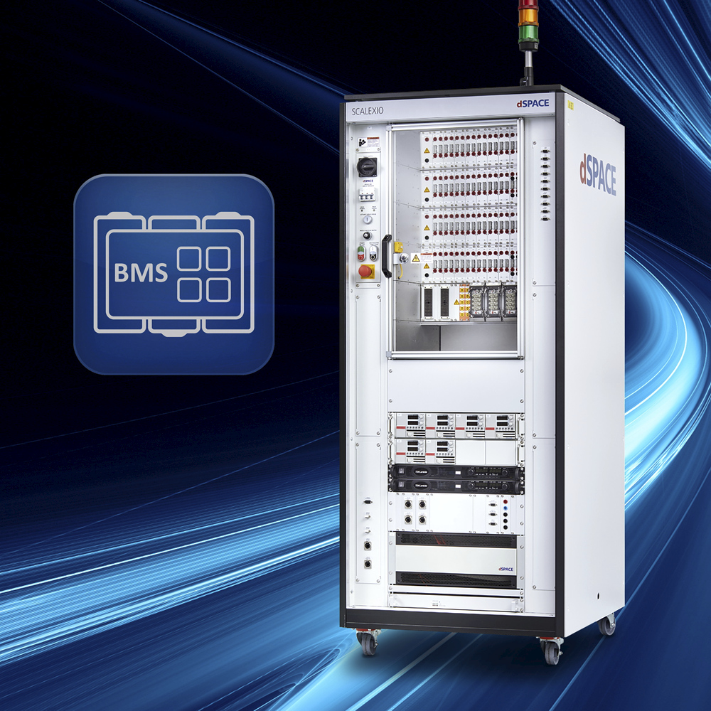
In the HIL phase, the real BMS hardware is connected to a real-time simulator running the battery model. This step verifies functional safety and real-world system behavior.
Typical tests include:
- Fault tolerant time interval (FTTI): Measuring response time to faults such as overvoltage
- Contactor diagnostics: Simulating failure modes such as welded contactors
- Thermal derating: Testing system response to elevated temperatures and validating power limitation strategies
Additional process considerations
Electrical modeling and simulation are essential for reducing development time, minimizing physical testing, and improving system safety early in the design process.
- Short circuit and fault simulation are critical to ensure that protective elements such as fuses and contactors behave correctly under extreme conditions.
- EMI/EMC modeling is used to assess electromagnetic compatibility and prevent interference with other vehicle systems.
- Model accuracy and validation are key challenges. The quality of simulation results depends heavily on input data, parameterization, and the correct coupling of electrical and thermal effects.
- Scalability and complexity increase significantly when moving from cell-level to pack-level models, requiring efficient simulation tools and computing resources.
This is one stage of the full battery module development workflow
See how BMS, Busbar & Electrical Design fits into the end-to-end Battery Module Development journey.
Back to the full guide →