Battery Pack Assembly: What Matters and Why
Battery systems engineer Mahmoud Hermes walks through the ten stages of cylindrical battery pack assembly — what matters at each stage, why it matters, and what goes wrong when it is skipped.

 Switzerland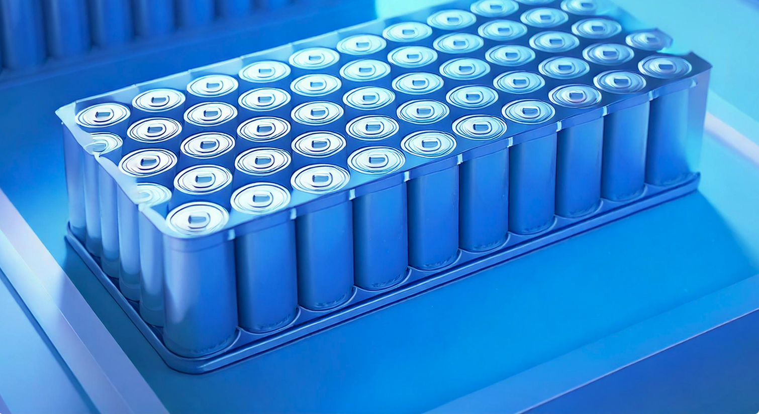
Most articles about battery pack assembly describe what happens. This one describes what matters, why it matters, and what goes wrong when it is skipped.
Every stage below reflects real production experience with cylindrical lithium-ion cells in high-reliability applications. The intent is not a recipe but a framework for engineering judgment.
Multiple cell formats exist, including cylindrical, pouch, and prismatic. This article covers cylindrical cells, which dominate high-power applications due to their mechanical robustness and high automation potential. The sequence below applies from the moment you receive the cells through delivery of a complete battery pack ready for shipment.
Stage 1: Incoming Cell Acceptance
Battery cells must be received and stored in a controlled environment. From a safety standpoint, every batch must be labeled "Untested" and must never reach the production floor without inspection first. In aviation, this process is called a First Article Inspection (FAI).
Cells typically arrive with a Certificate of Conformance and a datasheet. Neither is a substitute for incoming inspection. The certificate confirms the batch passed the manufacturer's internal tests at the time of production. It tells you nothing about what happened during shipping, how long the cells sat in a warehouse, or whether the specific units you received fall within the tolerance band your configuration requires.
The FAI works on a random sample: from a shipment of 50,000 cells, pull 100 to 300 cells at random and verify that their electrical parameters match what you ordered. The minimum test set is as follows.
Electrical tests
- Open Circuit Voltage (OCV)
- Internal Resistance (DC-IR or AC-IR)
- Delta-OCV (self-discharge indicator)
- Capacity verification (optional, depending on application)
Physical inspection
- Can geometry: any visible deformation of the can wall, dent, or asymmetry at the bead is a reject
- Positive cap: inspect for deformation or center pin displacement — damage here directly affects wire bond adhesion and current-carrying capacity
- Negative terminal contact area: assess any scratches, oxidation, or residue against your surface preparation plan
- Can wrapper: inspect for tears, punctures, or delamination
What counts as a good cell? Acceptance criteria are set by each company's quality standard, but typical targets look like this: for NMC chemistries, a maximum OCV variance across the batch of 2–5 mV; for LFP, 1–2 mV. For internal resistance, a total variance of 10% across the batch, with premium programs aiming at 5%.
Tight limits have real yield consequences: at an aerospace-grade 5 mV OCV limit, as much as a quarter of a shipment can fail incoming inspection. Rejected cells are isolated immediately and either returned to the supplier under the cell supply agreement or discarded in line with local regulations — they never enter production.
Stage 2: Cell Sorting
Once the FAI is approved and the batch is accepted, the label changes from "Untested" to "Verified and Ready for Production". Accepting the FAI does not mean every individual cell is in good condition — the FAI qualifies the batch on a sample; sorting checks every cell. Depending on your industry and risk tolerance, 100% electrical and physical inspection of all cells is strongly recommended to prevent any defective unit from entering production. In some industries, such as aerospace, full per-cell traceability is required by law.
Skipping this step has a long tail: cells that are out of tolerance produce unbalanced modules, and the BMS then works continuously to compensate — inefficient, and hard on the system over its whole life.
For low-volume manufacturing — around 2,000 cells, roughly the content of one pack — this can be done with benchtop fixtures and manual OCV and IR measurement of every cell, though it is labor-intensive. For higher volumes, automated bespoke machines equipped with vision systems read each cell's QR code, inspect can geometry, and run the full electrical test suite, sorting output into accepted and rejected bins. The precision and throughput of these machines is not comparable to manual methods.
Traceability starts here. Every cell that enters production must have its serial number or QR code scanned and linked to its measured OCV, IR, and grade bin before it advances to the next stage.
In practice this runs through the MES: cameras record each cell's QR code; the cell manufacturer's per-cell OCV and IR data (usually a CSV export) is merged with your own incoming measurements; and every cell is then mapped to its module, and every module to its pack — down to the exact position, if you take it to that level. In a recall, you know exactly which packs contain cells from an affected batch. If you cannot trace a cell from its position in the finished pack back to its incoming test data, you cannot perform a meaningful root cause analysis when something goes wrong — you are blind.
Stage 3: Cell Loading
After sorting, cells are loaded into the carrier, commonly referred to as the honeycomb or cell holder. The carrier design varies between manufacturers and serves multiple functions: mechanical support, cell spacing, and in some designs, a pathway for side cooling.
Cell orientation must be controlled and verified at this stage. Some designs, such as the Lucid architecture, orient all cells in the same direction to present a flat bottom surface optimized for direct base cooling. Other designs, common in home storage products, alternate positive and negative terminals across both faces. Whichever approach your design requires, a dedicated quality check must confirm correct orientation before the assembly advances.
For low-throughput lines, manual loading with a two-man verification rule is acceptable, where each operator checks the other's work. For higher-throughput lines, an automated vision system with a go/no-go output, compared against a stored reference pattern, is the appropriate upgrade.
Stage 4: Surface Treatment
Battery cell terminals and can surfaces as delivered are not ready for bonding, welding, or adhesive application. The surface condition determines the quality and long-term reliability of every electrical and mechanical joint in the module. Three methods are available, each with a different capability level and production fit.
Chemical cleaning (IPA or acetone, manual) is acceptable only for one-off prototypes where a single engineer controls the entire process. It is not suitable for production due to poor repeatability, invisible solvent residue risk, and health and fire hazard requirements.
Plasma treatment (atmospheric plasma, inline or handheld) is the production-standard method for most cylindrical cell terminal applications. UV photon bombardment removes organic contamination while ionic bombardment reduces the surface oxide layer, producing a clean, high-energy surface that wets uniformly and bonds reliably. It is suitable for flat terminal contacts and compatible with wire bonding and adhesive processes.
Laser cleaning (pulsed fiber laser, ablation) carries a higher capital cost than plasma but offers superior spatial precision, cleaning exactly the bonding zone without affecting the wrapper or surrounding geometry. It is best suited for prismatic cell terminals or cylindrical positive caps with complex geometry, and it can be integrated with a laser welding station, reducing equipment footprint and capex to a single machine.
Process requirements: both plasma and laser cleaning require enclosed equipment with appropriate extraction systems. Plasma treatment generates fumes that present a long-term respiratory hazard if not properly controlled — the machine must operate in a closed enclosure with active extraction. Laser systems require a laser-class-appropriate enclosure and operator eyewear matched to the specific wavelength and power class of the equipment.
Stage 5: Cooling System Attachment
Cooling in a battery module is not a single assembly step. It is a sequence of operations distributed across the production line, and where each operation falls depends entirely on your thermal architecture.
Side cooling panels are installed during or immediately after cell loading, before the electrical connections are made. Bottom cooling plates are attached after module assembly is complete. Foam or phase-change materials injected between cell rows are applied after cell connection. If your design uses more than one cooling method, this stage repeats at multiple points on the line. Plan your assembly sequence around your thermal architecture from the start, not as an afterthought.
Verification happens mostly at part level, and that is deliberate. Every cooling pipe is sealing- and pressure-tested before it is released to the production floor — that test qualifies the part. A further test of the active cooling circuit runs at the end of the line. A full closed-loop leak test on an assembled pack is possible but expensive and hazardous, which is why part-level qualification carries the weight. Foam and immersion systems can barely be inspected after assembly at all — endoscopy of a module is the rare exception — so for these, process control up front is the only real protection.
The consequence of getting this stage wrong is not an immediate failure. It is a thermal failure six months into operation, when cells that should be running at 45°C are running at 62°C because a cooling interface was applied incorrectly, incompletely, or out of sequence.
Stage 6: Cell Connection
Once cells are loaded and cooling interfaces are in place, the cells must be electrically interconnected. This is done through busbars and cell-level interconnects working together. The busbar carries current between groups of cells and between modules. The cell-level interconnect is the joint between each individual cell terminal and the busbar — and the choice of method here defines your process, your safety architecture, and your production line investment. Three methods are used in production.
Resistance spot welding — a high-current pulse fuses a nickel or nickel-plated steel strip directly to the cell terminal using two electrodes pressed against the contact surface.
- Advantage: lowest capital cost and simplest line integration; the dominant method in consumer electronics and home storage products by total unit volume
- Disadvantage: high heat input directly into the cell terminal and no inherent fusing function, requiring a separate overcurrent protection layer
Laser welding — a focused laser beam melts and fuses a metal interconnect tab or busbar directly to the cell terminal with precise energy control.
- Advantage: low heat input, high joint repeatability, and compatibility with aluminum and copper interconnects, making it the standard in high-volume automotive EV production
- Disadvantage: high capital cost and the need for validated welding recipes per terminal type, with sensitivity to surface contamination causing weld defects
Wire bonding — ultrasonic bonding attaches individual aluminum ribbon wires from each cell terminal to a busbar or PCB pad. Each wire is a discrete, independent connection.
- Advantage: each wire acts as an inherent fuse, providing per-cell overcurrent protection and automatic fault isolation without any additional components — which is why it is increasingly specified in aerospace and high-voltage automotive applications
- Disadvantage: lower throughput per connection compared to a welded strip, and mandatory surface pre-treatment (plasma or laser cleaning) before bonding, adding a process dependency that must be tightly controlled
Stage 7: Module-Level Electrical Verification
Once cell connection is complete, the module exists as a single electrical unit for the first time. Before any further assembly progresses, it must be verified. This step is not optional and is not a formality: the cost of finding a fault here is a rework at the module level. The cost of missing a fault here is a teardown of a finished pack — or worse, a field failure.
Verification at this stage covers three things. First, confirm every cell voltage is present and reading within the expected window, using a BMS slave board connected to a laptop or test rig. Second, confirm every temperature sensor is responding with a plausible value. Third, perform a visual inspection of every cell connection — wire bond, ribbon, or laser weld — checking for missing bonds, lifted joints, cold welds, or any connection that looks different from the others.
All three checks must pass before the assembly advances. A module with a missing bond, an open sensor circuit, or a dead cell group is far cheaper to fix on the bench than inside a sealed enclosure with busbars torqued down and thermal compound cured.
Expect a share of modules to fail this first verification — around 5% is a realistic figure in the author's experience, most often because a bond did not go through or a BMS connection is incorrect. Failed modules are segregated, reworked at a separate station, re-verified by quality, and only then released into a pack. Modules with housing damage or missing parts are not always reworkable.
Set up a dedicated test rig for this station. It does not need to be complex: a BMS slave board, a harness matched to your module connector, a laptop running the BMS software, and a written acceptance checklist. The rig pays for itself the first time it catches a fault before it becomes a pack-level problem.
Stage 8: Battery Pack Structure Assembly
With multiple modules built and verified, they are ready to be stacked into the pack structure. How you stack them depends on your pack design and where the cooling sits. You can stack modules on top of each other. Some builders keep the pack very flat, which is common in automotive because the pack becomes part of the vehicle structure. Others end up with unusual shapes when space is tight, as in Formula cars or hypercars. The shape varies, but the step matters either way.
In the author's experience, a semi-automated line covers roughly 2,000 to 5,000 packs per year. At OEM-scale volumes — around 20,000 to 30,000 packs per year and beyond — a robotic station keeps people away from a high-voltage assembly, and there is no realistic path to those volumes without robots at multiple stations. At lower volume the same result is achieved manually, with arc-flash-rated PPE in place for everyone working on the live assembly.
Stage 9: Battery Pack Testing
After stacking comes an important test on the pack structure to check the sealing. This is normally done with helium, pressurizing the pack with gas to confirm there are no leaks. Some builders use plain air pressure instead and watch the pack over time to see whether any leak develops. Testing the pack before it leaves the line is standard practice.
Stage 10: Battery Pack Charging
Once the modules and the pack are assembled and both have been tested, the pack needs its first electrical cycle. Here it goes on the charging station for the first time: run one full charge and discharge cycle, then charge the pack to a specific SOC depending on where it is headed next. If it is going straight to vehicle assembly on your premises, that might be around 45 percent.
Through all of these steps it is critical to trace every component of the battery, from each individual cell to every part, on the MES. For any recall or defect you need to be able to trace a component back to its batch, its shift, and the exact day it was built.
I hope this gives you a glimpse of how a battery pack is built. If you have any questions, or want recommendations on machines or partners for building your line, feel free to reach out.
Equipment Recommendations
The author's shortlist of suppliers he has worked with or vetted, by process step:
- Cell testing (automated and manual): Hioki
- Line transfer and pallets: Bosch Rexroth TS 2plus — boschrexroth.com
- Robotics: choose a supplier with real on-the-ground support — commissioning a robot is as much about grippers and troubleshooting as programming. Established options: Fanuc, KUKA, Universal Robots
- Automated cell sorting: S4 — South Africa based with European and US presence; the author recommends them from direct experience for pricing, responsiveness, and bespoke machine design. Also Müller Technology — Swiss with a US presence, bespoke machines including plasma cleaners; higher priced, very responsive
- Plasma cleaning: Tigres — plasma generates toxic gases, and this unit ships with a full filtration system, specifically for ozone
- Wire bonding: F&K Delvotec — bond testing integrated at the bond head, multiple bed sizes. Also Hesse Mechatronics — bed sizes up to 1 m; through Hesse Electronics, machine time can be rented at reasonable cost, useful for young companies that cannot yet justify the capex (available in the US)
- Laser bonding: Trumpf
- Shear and pull testing: for wire bonding, shear and pull tests are required at minimum once per shift — ideally before the shift starts, to qualify the machine and the wire. Nordson offers manual through automated machines; XYZTEC is also strong in this space
- Pack seal testing: Marposs — air or helium; helium is more accurate and more expensive
- Laser cleaning: Laserax — reliable delivery at a reasonable price for the quality
- Complete production lines (A to Z): PIA Automation — OEM-scale budgets in the millions, not aimed at small companies
Related Products & Solutions

Prismatic Battery Module & Pack Assembly Line

Battery Thermal Runaway Mitigation Tapes

.png%3F2026-04-06T15%3A31%3A05.323Z&w=3840&q=100)
Dielectric Insulation Tapes for Battery Systems

Battery Module Scanner BattScan050M
